Ni-Wumpf System 1 CPU Reset Generator Modification


Back in Oct. 2007, I was working on a Gottlieb Count-Down.  After repinning all of the necessary connectors, I installed a Ni-Wumpf CPU and a Rottendog power supply.  While I was working on the game with the new boards installed, I turned the game off, and turned it back on rather quickly.  At that point, the game exhibited some strange behavior.  Several segments of the displays had locked on.  I discounted what had happened, and continued working.  A few minutes later, I again quickly turned the game off and then on.  This time I saw lamps locking on, and heard a couple of coils locking on.  After trying this several times, the same type of results would occur.  Either the displays, lamps, coils, or any combination of all three would lock on upon quick cycling the power switch to the game.  This resulted in a phone call to Ace at Ni-Wumpf.

After describing the issue to Ace, he recommended I replace the 47uF 16v cap used in the reset section.  He mentioned that the particular board I had may have a bad cap.  So, I swapped out the old cap, but had the same results.  This had Ace and I scratching our heads.  I went over everything I did to the game, and there was nothing different with this System 1 than any other System 1 I had done previously.  We ended our conversation at that point.

Since I really like to know the answer to any problem, I decided to "quick cycle" the power on the Sinbad I owned.  The Sinbad had an older Ni-Wumpf CPU and a Great Plains Electronics (GPE) power supply installed.  I saw the same results with Sinbad as I did with Count-Down.  All right, I now have two games with aftermarket boards, and both act up when I turn them off and on quickly.  This is not good at all.

The problem prompted me to put a call into Ed K. @ GPE, and see if he could figure out what was going on here.  I was convinced it was an issue with the new power supplies.  I explained the situation to Ed.  Upon reviewing the Ni-Wumpf CPU schematics, Ed promptly replied with the answer, "The Ni-Wumpf board has a power-up reset but does not have a power monitoring circuit. The existing power-up reset would generate a proper reset only when the power supply is starting from zero or near zero volts.  A power monitoring circuit would generate a reset whenever the power is out of proper operating range."
 
With the old fashioned linear type power supplies, the power monitoring circuit was not required due to the heavy load and slow turn on time of the power supply.  The Ni-Wumpf board was given ample time to clear the power-up reset circuit such that the reset was working properly.  The new style power supplies have fast turn on times.  This fast turn on time was causing the problems with the Ni-Wumpf board.  When the power supply was quickly turned off and back on again - there would only be a small dip in the +5V supply.  This dip was not low or long enough to clear the existing Ni-Wumpf power-up reset, but it was long and low enough to put the CPU into an unknown state - a 'lost CPU' condition.  A power monitoring circuit would see these quick power dips, and cause a reset to the CPU thus fixing the problem.

Ed came up with the idea of adding a reset generator (MCP120-460GI/TO) as shown below.  The Rev. C board is what was used at first, just to see if this would work.  Success!!!  The CPU no longer booted until the voltage reached a specific voltage.  No more lockups!!!  Thank you, Ed!!!

I then followed up with Ace, explained what Ed had suggested, and why this problem was occurring.  Ace quickly understood why it was happening.  When he designed the Ni-Wumpf CPU 15 or more years ago, there weren't any aftermarket power supplies available at the time.  According to Ace, this strange anomaly has never been apparent while using a stock Gottlieb power supply.  So, please keep in mind that this modification is only necessary when an aftermarket power supply is used in conjunction with a Ni-Wumpf CPU board.

Below are illustrations of the modified Rev. C Ni-Wumpf board, a stock Rev. F Ni-Wumpf board, and a Rev. F Ni-Wumpf board modified with the reset generator.  The reset generator used on the Rev. F board was an MCP130-460HI/TO available from GPE.  For the Rev. C Ni-Wumpf board, the MCP120-460DI/TO would be better suited for this application.

A big thank you goes to Ed K. @ GPE.  Ed resolved the issue, I only executed his resolution.  Also, a big thanks to Ace @ Ni-Wumpf for the continued support of his replacement CPU boards.

01_NiW_Rev_C_After_Front.JPG.png
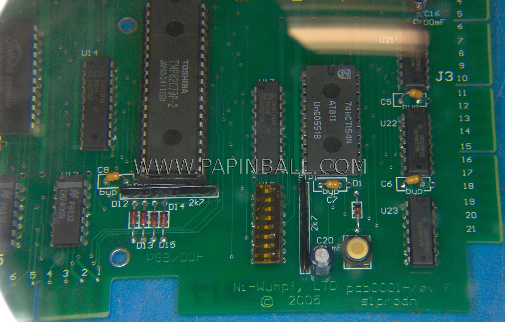
A Rev. C CPU board where the 47uF 16v reset capacitor was replaced by the MCP120-460GI/TO reset generator.  The use of an MCP120-460DI/TO would be much better suited.  When using the DI configuration, please note that the reset generator would be turned 180 degrees, (the flat side would be facing the dipswitch bank). 
02_NiW_Rev_C_After_Back.JPG.png
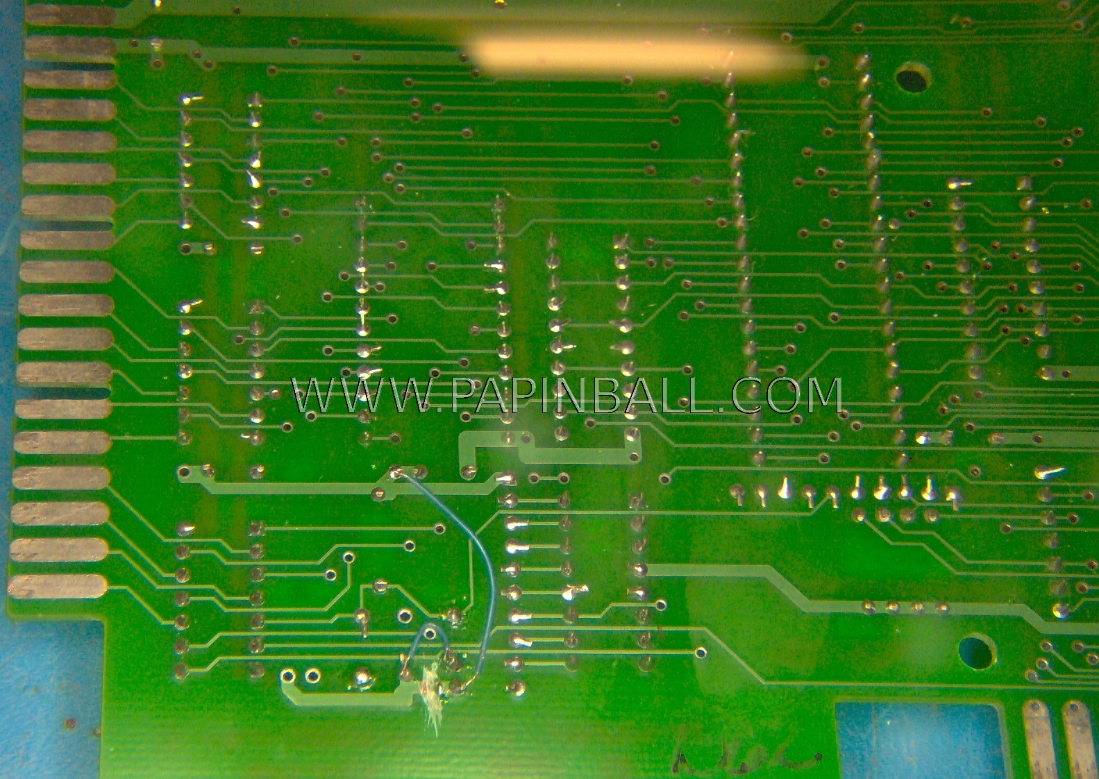
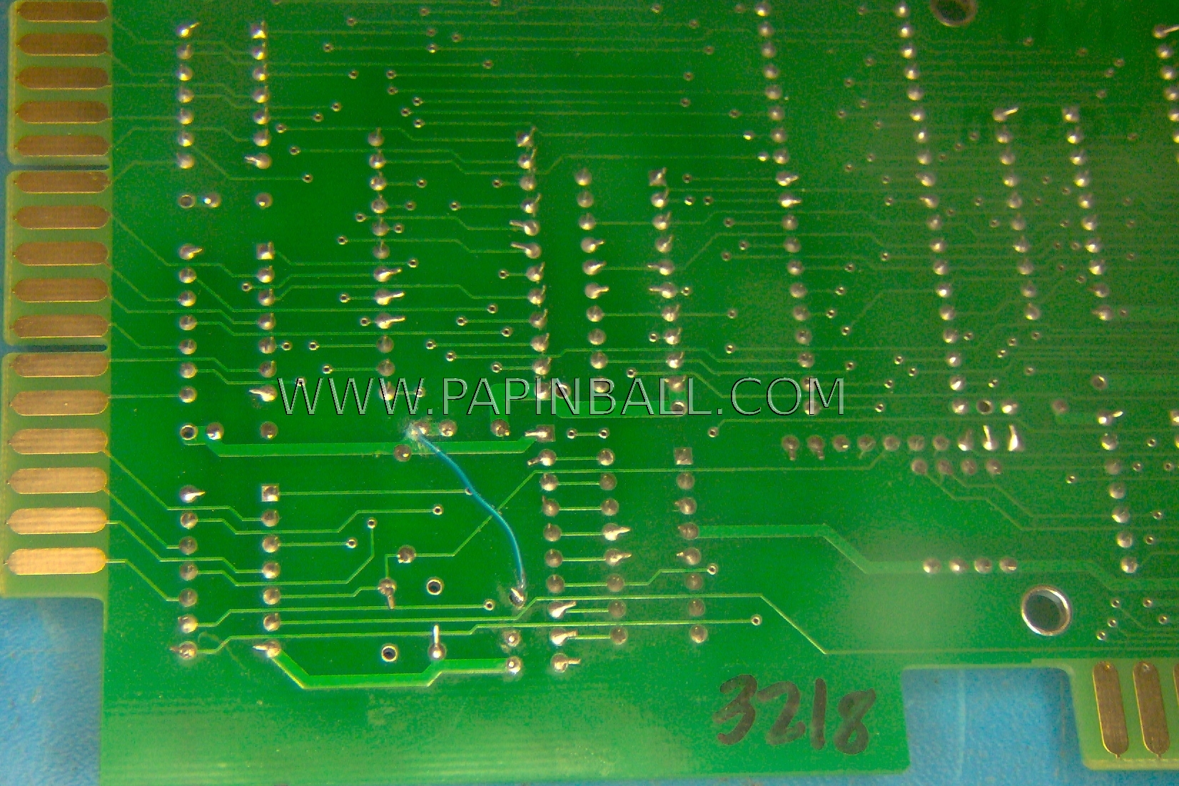
The same Rev. C CPU board shown.  A trace had to be cut, and wire wrap was used to pick up the correct signals.  A reset generator with a better pinout would have probably worked much better.  However, this is when the project was in its infant stage.

The use of an MCP120-460DI/TO has a more appropriate pinout.  When using the DI version, no traces would need to be cut.  Only a wire wrap from the +5vdc bus to the center leg of the reset generator would need to be added.
03_NiW_Rev_F_Before_Front.JPG.png
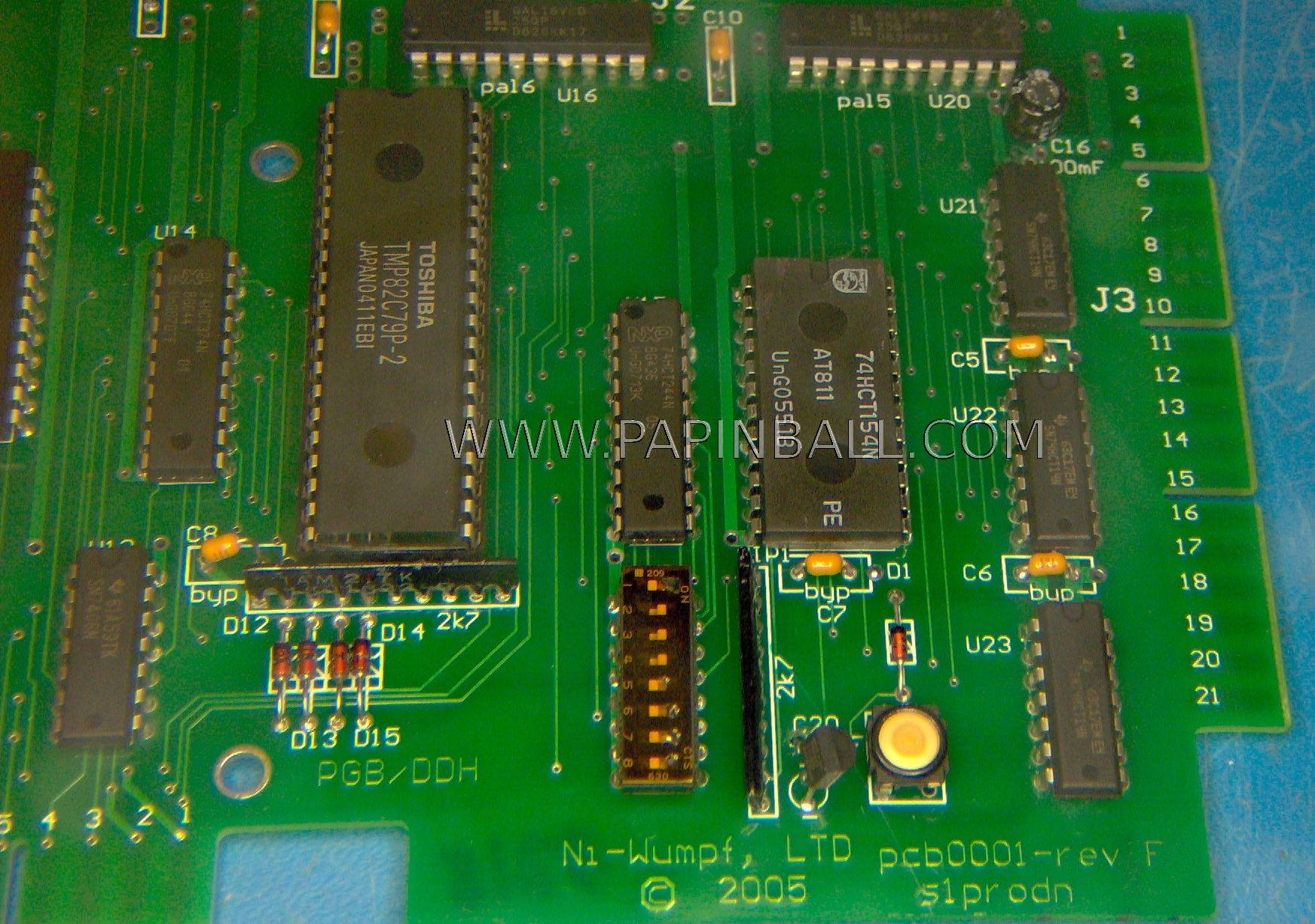
A stock Rev. F CPU board, (the most current revision as of this writing in 2010), with the C20 47uF 16v reset capacitor still intact.
04_NiW_Rev_F_Before_Back.JPG.png
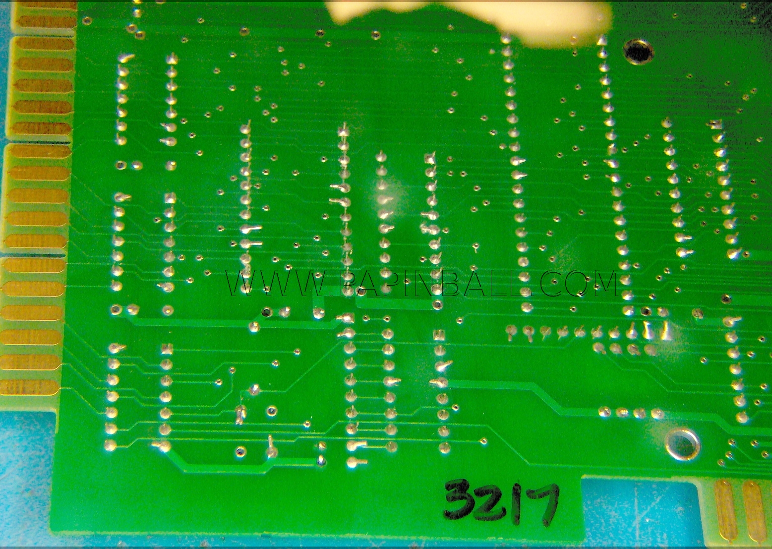
The same stock Rev. F CPU board with reset capacitor still intact.
05_NiW_Rev_F_After_Front.JPG.png
A modified Rev. F CPU board where the MCP130-460HI/TO reset generator has replaced the C20 47uF 16v reset capacitor.  A hole had to be drilled in the board for the Vcc leg of the reset generator.  A 1/16" hole was drilled in this example.  Although, a smaller hole would be better suited.
06_NiW_Rev_F_After_Back.JPG.png
The same modified Rev. F CPU board.  A wire wrap was connected to the Vcc leg of the reset generator, and tied to a convenient through hole on the +5vdc bus line.


Home